DNS
DNS (Domain Name Server) is a distributed database that links various host names to specific Internet addresses. The DNS monitor determines the IP addresses of external and internal host names by matching a virtual host name to an expected IP address. If a match is made, the status of the service monitor is OK.
You can, for example, use the DNS monitor to:
- ensure that your audience can access your Web site or portal by making sure that a selected address can be resolved
- identify instances in your network environment where resources have had their IP addresses changed, and now the resource is no longer available
To collect performance information, the DNS monitor:
- opens a UDP socket to a DNS server
- creates a query packet
- sends the query packet
- waits for a response
- parses the answers
The DNS monitor does not check for the NS or MX records, which return names and not IP addresses. Non-authoritative answers as well as authoritative responses are used.
Before You Begin
Before configuring the DNS monitor, determine the IP address for the host that you want to monitor. For internal hosts, you can use the ipconfig command from the command line.
The ipconfig command returns information similar to the following:
| No Format | ||
|---|---|---|
| ||
Connection-specific DNS Suffix . . : uptimesoftware.com IP Address . . . . . . . . . . . . : 10.1.1.42 Subnet Mask . . . . . . . . . . . .: 255.255.255.0 Default Gateway . . . . . . . . . .: 10.1.1.1 |
For external hosts, you can use the nslookup command from the command line as follows:
| No Format | ||
|---|---|---|
| ||
nslookup <host name> |
The nslookup command returns information about the host, similar to the following:
| No Format | ||
|---|---|---|
| ||
Server: filter.uptimesoftware.com Address: 10.1.1.100 Name: uptimesoftware.com Addresses: 217.160.226.70, 10.1.1.95, 192.168.23.1, 192.168.190.1 |
Configuring DNS Monitors
To configure DNS monitors do the following:
- In the DNS monitor template, complete the monitor information fields.
To learn about monitor information fields, see Monitor Identification. - Complete the following fields:
- Hostname to Lookup
The host name that the monitor will check. The host name can be a Web site address, a server name, or a cluster name.
For example, for a Web site enter www.uptimesoftware.com in this field. - Port
The number of the port on which the DNS server is listening. The default is 53 . - IP Address
The IP address for which you want to check. If this address is not returned, the status of the service monitor becomes Critical. - Response Time
Enter the Warning and Critical Response Time thresholds for the amount of time required to complete a service check. For more information, see Configuring Warning and Critical Thresholds.
- Hostname to Lookup
- Click the Save for Graphing checkbox to save the data for a metric to the DataStore, which can be used to generate a report or graph.
- Complete the following settings:
- Timing Settings (see Adding Monitor Timing Settings Information for more information)
- Alert Settings (see Monitor Alert Settings for more information)
- Monitoring Period settings (see Monitor Timing Settings for more information)
- Alert Profile settings (see Alert Profiles for more information)
- Action Profile settings (see Action Profiles for more information)
- Click Finish.
FTP
The FTP monitor can determine:
- whether or not an FTP server is listening or is available on a specified port
- the response time of an FTP server
The FTP monitor tries to open an FTP connection to the server. If the response takes longer than the defined thresholds, up.time generates an alert.
Configuring FTP Monitors
To configure FTP monitors, do the following:
- In the FTP monitor template, complete the monitor information fields.
To learn how to configure monitor information fields, see Monitor Identification. - Complete the following fields:
- Port
The number of the port number on which the FTP server is listening. The default is 21 . - Server Response
Enter the Warning and Critical time thresholds required to receive a ready response from the FTP server. A server ready response can look like the following:
220 filter FTP server (Version wu-2.6.2(1) Mon Dec 3 15:29:55 EST 2005) ready - For more information, see Configuring Warning and Critical Thresholds.
- Response Time
Enter the Warning and Critical Response Time thresholds for the length of time that the service check takes to complete. For more information, see Configuring Warning and Critical Thresholds.
- Port
- Click the Save for Graphing checkbox to save the data for a metric to the DataStore, which can be used to generate a report or graph.
- Complete the following settings:
- Timing Settings (see Adding Monitor Timing Settings Information for more information)
- Alert Settings (see Monitor Alert Settings for more information)
- Monitoring Period settings (see Monitor Timing Settings for more information)
- Alert Profile settings (see Alert Profiles for more information)
- Action Profile settings (see Action Profiles for more information)
- Click Finish .
HTTP (Web Services)
The HTTP (Web Services) monitor simulates the steps that you take to access a Web site. Using this monitor, you can verify several things:
- you can access a Web site using HTTP
- you can log on to a Web site
- a Web site is running according to your expectations
You can determine this by examining the values that are returned from the Web server.
The HTTP (Web Services) monitor relies on a Universal Resource Identifier (URI), which defines a specific file location on a Web server. This monitor can test for application calls, database responses, or any other information that a URI can return.
Configuring HTTP (Web Services) Monitors
To configure HTTP (Web Services) monitors, do the following:
- In the HTTP (Web Services) monitor template, complete the monitor information fields.
- To learn about monitor information fields, see Monitor Identification.
- Complete the following fields:
- URI
The URI of the Web page that you want to monitor. For example,
/login.php . - Text to Look For (Optional)
Enter the text that you want the monitor to search for in the response from the server.
This monitor parses the text from the server and, using the threshold values you enter, determines if the entire Web page returned by the server is within acceptable parameters.
For example, if a Web page is returned then the monitor parses the entire page for the text that you input to match against. If you want to ensure that a particular page is returned, you could enter <TITLE>Expected Page</TITLE> , where Expected Page is the title of the Web page. The monitor generates an alert if this page is not matched. - Authentication
The user ID and password, in the form userid:password . For example:
jlamport:bluefrog5 - Virtual Host
The unique domain name that resolves to the IP address of the domain that you want to monitor. A virtual host has its own domain name, but has the same IP address as other domain names hosted by the Web server. - Server Response
Enter a string to match against the response from the server. For example, HTTP/1.1 200 OK or HTTP 404 - File not found . Then, set the Warning and Critical comparison methods. For more information, see Configuring Warning and Critical Thresholds - Follow Redirect Actions
Select an action that enables you to specify whether or not you want to be redirected to another Web address:- OK
Return an OK status for any re-direction. - Follow
Follow any re-direction. - Warning
Return a Warning status for any re-direction. - Critical
Return a Critical status for any re-direction.
- OK
- POST String
The URL-encoded POST string to be sent to the server. This string simulates what a Web browser sends to a Web server CGI script or binary. You can use the POST string to, for example, simulate logging into a Web application.
For example, if you define the POST string as userid=bob&sku=123456 , the page to request would be /cgi-bin/sku_lookup . The text “ SKU count is ” is the expected response. If the SKU lookup is not successful or if the response from the application server is not fast enough, then up.time generates an alert. - Set-Cookie String
The parameters that define the cookie. The cookie string uses the following format:
domain:name:value:path
If configuring multiple cookies for the monitor, separate each cookie string with a semicolon:- domain is the subdomain the cookie is available to.
- name is a name with which you can later reference the cookie.
- value is a regular string to be stored as a cookie. The string should be encoded using URL-style %xx encoding, which converts all reserved and unsafe characters - such as tildes (~) and spaces - to their ASCII equivalents.
For example, using %xx encoding, the URL http://www.mydomain.com/~jdoe/index.html becomes http://www.mydomain.com/%7ejdoe/index.htmlpath is the location on the server in which the cookie has been made available. For example, if the path is “ / ” the cookie is available to the entire domain, as opposed to a specific subdirectory name.
d1:n1:v1:p1;d2:n2:v2:p2
The name and value pair is the only required attribute of the Set-Cookie String field.
- HTTP Header Settings
The HTTP header settings for the response.
The HTTP header settings define the syntax and semantics of all standard HTTP/1.1 header fields. For entity header fields, both sender and recipient refer to either the client or the server, depending on who sends and who receives the entity. - Response Time
Enter the Warning and Critical Response Time thresholds. For more information, see Configuring Warning and Critical Thresholds
- URI
- Click the Save for Graphing checkbox to save the data for a metric to the DataStore, which can be used to generate a report or graph.
- Complete the following settings:
- Timing Settings (see Adding Monitor Timing Settings Information for more information)
- Alert Settings (see Monitor Alert Settings for more information)
- Monitoring Period settings (see Monitor Timing Settings for more information)
- Alert Profile settings (see Alert Profiles for more information)
- Action Profile settings (see Action Profiles for more information)
- Click Finish.
IMAP (Email Retrieval)
The IMAP (Email Retrieval) monitor confirms whether an IMAP server is doing the following:
- listening on a defined port
- running on a defined system or on a group of systems
- using a particular version
Configuring IMAP (Email Retrieval) Monitors
To configure IMAP (Email Retrieval) monitors, do the following:
- In the IMAP (Email Retrieval) monitor template, complete the monitor information fields.
To learn how to configure monitor information fields, see Monitor Identification. - Complete the following fields:
- Port
The number of the port on which IMAP is listening.
The default is 143 . If you are applying a monitor to a service group, ensure that all of the systems use the defined port. Otherwise, create a monitor for each IMAP instance that listens on a different port.
For information on service groups, see Service Groups. Server Response
Select a comparison method, and then enter the Warning and Critical thresholds for the server response. For more information, see Configuring Warning and Critical Thresholds.
The server response is the same for Windows, UNIX, and Linux. For example, an expected response is:No Format nopanel true +OK [CAPABILITY IMAP4REV1 LOGIN-REFERRALS STARTTLS AUTH=LOGIN] filter IMAP4rev1 2002.336 at Thu, 2 Jun 2005 10:55:02 -400 (EDT)
If IMAP is not available, then the following is an expected response:
No Format nopanel true BAD Null command
By making string comparisons on the returned values to the monitor, you can check:- The version of IMAP that is running to support your network routing.
- The system on which IMAP is or is not running.
- Response Time
Enter the Warning and Critical Response Time thresholds for the length of time a service check takes to complete. For more information, see Configuring Warning and Critical Thresholds.
- Port
- Click the Save for Graphing checkbox to save the data for a metric to the DataStore, which can be used to generate a report or graph.
- Complete the following settings:
- Timing Settings (see Adding Monitor Timing Settings Information for more information)
- Alert Settings (see Monitor Alert Settings for more information)
- Monitoring Period settings (see Monitor Timing Settings for more information)
- Alert Profile settings (see Alert Profiles for more information)
- Action Profile settings (see Action Profiles for more information)
- Click Finish.
LDAP
LDAP (Lightweight Directory Access Protocol) is a protocol that organizes directory hierarchies and enables communication with directory servers. Individuals in an organization can use LDAP to search for information, files, or devices in a network.
The LDAP monitor can check for any settings or information in your LDAP directory. The monitor can start the check from any location within your LDAP directory structure.
The LDAP monitor attempts to match information that you have specified with information available in your LDAP directory. If the monitor finds the information, the service monitor returns a status of OK. Otherwise, the monitor returns a Critical error and up.time generates an alert.
| Info |
|---|
Note - If you do not specify any parameters, then this monitor only validates that an LDAP server is listening on the specified port. |
Before You Begin
To configure the LDAP monitor, you should understand how an LDAP directory works, and know how LDAP is configured in your environment. You can use the following tools to determine the Base, Bind, and Attribute values of the LDAP directory for which you want to search:
- at the Windows command line, use ntdsutil.exe to retrieve information
- one of the many freely-available LDAP browsing and editing tools
- your own network documentation and determine whether or not the proper configurations have been maintained
Configuring LDAP Monitors
To configure LDAP monitors, do the following:
- In the LDAP monitor template, complete the monitor information fields.
To learn how to configure monitor information fields, see Monitor Identification. - Complete the following fields:
- Port
The number of the port number on which the LDAP server is listening. The default is 389 . - Password
The password that is required to log in to the LDAP server. - Base
The location in the LDAP directory from which you want the monitor to begin searching for information.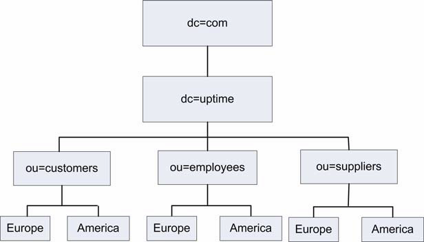
Using this directory structure, you can check your LDAP structure for your European employees by selecting the following as your base:
dc=ldap,dc=uptime,ou=employees,ou=Europe - Bind
The Bind string, which associates user account properties and LDAP account attributes. This string gives you access to the Base location of your LDAP directory structure.
The format of the Bind string must match the Base location of your LDAP directory structure. For example, if you are checking for information found below the European employees directory, you can
use the following Bind string:
cn=ldapadmin,dc=ldap,dc=uptime,dc=com
Depending on your network security model, you will need domain controller administration privileges to bind to the locations on which you want to match information. - Attribute
The attribute or information for which you want to search in your LDAP directory.
An LDAP entry consists of a set of attributes. Each attribute has a type - which describes the kind of information contained in the attribute - and one or more values, which contain the actual data. For example, the entry [email protected] has the Attribute value [email protected] . The Attribute type is e-mail . - Response Time
Enter the Warning and Critical Response Time thresholds. For more information, see Configuring Warning and Critical Thresholds.
- Port
- Click the Save for Graphing checkbox to save the data for a metric to the DataStore, which can be used to generate a report or graph.
- Complete the following settings:
- Timing Settings (see Adding Monitor Timing Settings Information for more information)
- Alert Settings (see Monitor Alert Settings for more information)
- Monitoring Period settings (see Monitor Timing Settings for more information)
- Alert Profile settings (see Alert Profiles for more information)
- Action Profile settings (see Action Profiles for more information)
- Click Finish.
NFS
NFS (Network File System) enables UNIX and Linux systems to share directories across a network. The NFS monitor can determine the performance of your NFS (Network File System) server and its ability to communicate with NFS clients by measuring the available NFS mounts.
This monitor runs the showmount -e command to extract the number of NFS file systems that are exported. If the showmount command fails, then up.time generates an alert.
| Info |
|---|
The NFS monitor is currently not supported on Windows 7 SP1 running on 64-bit platforms. |
Configuring NFS Monitors
To configure NFS monitors, do the following:
- In the NFS monitor template, complete the monitor information fields.
To learn how to configure monitor information fields, see Monitor Identification. - Complete the following fields:
- Mounts
Select a comparison method, and then enter the Warning and Critical Mount thresholds for the number of mounts on which NFS is loaded. For more information, see Configuring Warning and Critical Thresholds. - Response Time
Enter the Warning and Critical Response Time thresholds for the length of time a service check takes to complete. For more information, see Configuring Warning and Critical Thresholds.
- Mounts
- Click the Save for Graphing checkbox to save the data for a metric to the DataStore, which can be used to generate a report or graph.
- Complete the following settings:
- Timing Settings (see Adding Monitor Timing Settings Information for more information)
- Alert Settings (see Monitor Alert Settings for more information)
- Monitoring Period settings (see Monitor Timing Settings for more information)
- Alert Profile settings (see Alert Profiles for more information)
- Action Profile settings (see Action Profiles for more information)
- Click Finish.
NIS/YP
NIS/YP (Network Information Services/Yellow Pages) is a distributed database system that enables you to configure multiple hosts from a central location as well as store and maintain common configuration information in that location. You can then propagate the information to all of the nodes in a network. The collection of network information is referred to as the NIS namespace .
The NIS/YP monitor performs a lookup on the domain, table, and key, enabling you to:
- check that a Network Information Service (NIS) server for a given domain is responding
- request a specific key from a NIS table. This is useful if the contents of the NIS maps are often rebuilt
Configuring NIS/YP Monitors
To configure NIS/YP monitors, do the following:
- In the NIS/YP monitor template, complete the monitor information fields.
To learn how to configure monitor information fields, see Monitor Identification. - Complete the following NIS/YP monitor settings:
- YP/NIS Domain
The domain of the NIS service. For example, uptimesoftware.com . NIS administration databases that contain name service information are called maps . A domain is a collection of systems that share a common set of NIS maps. - YP/NIS Table
The name of the NIS/YP table that contains the values for which you want to search. Key
Enter a value you want to search for in the NIS table. For example, the key is jsmith in the following string returned from a NIS table:No Format nopanel true jsmith:LLZDusFe5Da3s:20080:100:Jim Smith:/export/home/jsmith:/bin/sh
Lookup
The Lookup value associated with the value in the Key field. For example, the following is returned from the passwd table of a NIS database based on the key jsmith :No Format nopanel true jsmith:LLZDusFe5Da3s:20080:100:Jim Smith:/export/home/jsmith:/bin/sh
- Response Time
Enter the Warning and Critical Response Time thresholds for the length of time that a service check takes to complete. For more information, see Configuring Warning and Critical Thresholds.
- YP/NIS Domain
- Click the Save for Graphing checkbox to save the data for a metric to the DataStore, which can be used to generate a report or graph.
- Complete the following settings:
- Timing Settings (see Adding Monitor Timing Settings Information for more information)
- Alert Settings (see Monitor Alert Settings for more information)
- Monitoring Period settings (see Monitor Timing Settings for more information)
- Alert Profile settings (see Alert Profiles for more information)
- Action Profile settings (see Action Profiles for more information)
- Click Finish.
NNTP (Network News)
NNTP is a protocol for distributing, searching, retrieving, and posting of messages and news articles from USENET (a global collection of online discussion groups). NNTP stores content in a central database, enabling subscribers to select only the messages and articles that they want to read.
The NNTP (Network News) monitor measures the performance of your NNTP server. It can also determine the server status in terms of the following:
Command Implementation
Status reports from the server indicate the response to the last command that was received from the client. Status response lines begin with a three-digit numeric code, which is used to distinguish between all responses.
The first digit of the response broadly indicates the success, failure, or progress of the previous command:
- 1xx - an informative message
- 2xx - the command is OK
- 3xx - the command OK to this point, but the rest of it will be sent
- 4xx - the command was correct, but could not be carried out
- 5xx - the command is not implemented, or it is incorrect, or a serious program error has occurred
Response Category
The next digit in the status response code indicates the function response category.
- x0x - connection, setup, and miscellaneous messages
- x1x - newsgroup selection
- x2x - article selection
- x3x - distribution functions
- x4x - posting
- x8x - nonstandard extensions
- x9x - debugging output
Response Codes
The following is a list of general response codes that may be sent by an NNTP server. These are not specific to any one command, but may be returned as the result of a connection, a failure, or an unusual condition.
- 100 - help text
- 190 through 199 - debugging output
- 200 - the server is ready and posting is allowed
- 201 - the server is ready, but no posting is allowed
- 400 - service has been discontinued
- 500 - the command is not recognized
- 501 - a command syntax error occurred
- 502 - an access restriction or permission is denied
- 503 - a program fault occurred and the command was not executed
You can ignore 1xx codes. Code 200 or 201 is sent upon initial connection to the NNTP server, depending upon the posting permission. Code 400 is sent when the NNTP server discontinues service - for example, by request of the operator. The 5xx codes indicate that the command could not be performed for some unusual reason.
Configuring NNTP (Network News) Monitors
To configure NNTP (Network News) monitors, do the following:
- In the NNTP (Network News) monitor template, complete the monitor information fields.
To learn how to configure monitor information fields, see Monitor Identification. - Complete the following fields:
- Port
The number of the port on which the NNTP server is listening. The default is 119 . - Server Response
The server response according to the value that you want to measure.
For information on command implementation, see Command Implementation.
For information on response categories, see Response Category.
For information on general response, see Response Codes.
- Port
- Response Time
Enter the Warning and Critical Response Time thresholds. For more information, see Configuring Warning and Critical Thresholds. - Click the Save for Graphing checkbox to save the data for a metric to the DataStore, which can be used to generate a report or graph.
- Complete the following settings:
- Timing Settings (see Adding Monitor Timing Settings Information for more information)
- Alert Settings (see Monitor Alert Settings for more information)
- Monitoring Period settings (see Monitor Timing Settings for more information)
- Alert Profile settings (see Alert Profiles for more information)
- Action Profile settings (see Action Profiles for more information)
- Click Finish.
Ping
The Ping monitor determines whether or not you can communicate with other IP addresses or domain names. The Ping monitor can check the following:
- whether or not you can reach a specified system
- the amount of time required to bounce a packet off of another site
You will receive a response if the connections are good and the target system is running. If you have successfully pinged a system in the past, but you cannot get a response, there is a problem either with the network or with the system. If it takes a long time for a ping to return, the network or system may be extremely busy.
The ping program sends a small packet of information containing 64 bytes - 56 bytes of data and eight bytes of protocol reader information. The computer that sent the packet listens for a reply from the specified IP address. The ping program then evaluates this reply, and up.time captures the report that the program displays.
Configuring Ping Monitors
To configure Ping monitors, do the following:
- In the Ping monitor template, complete the monitor information fields.
To learn about monitor information fields, see Monitor Identification. - Complete the following fields:
- Number to send
The number of packets to send to an IP address or domain name.
This value determines the number of times the ping command attempts to contact a server. - Average Round Trip Time
Enter the Warning and Critical thresholds for the average round trip time for the number of packets sent by the ping command. The round trip time is in milliseconds.
This value is a good indicator of ping performance because a variety of factors - including different packet paths to and from the server - can affect the round trip time of a packet. - Percent Loss
Enter the Warning and Critical thresholds for the number of packets that did not returned a reply. For example, if four packets were sent and only two are returned, the percent loss is 50%. - Response Time
Enter the Warning and Critical Response thresholds for the length of time the service check takes to complete. For more information, see Configuring Warning and Critical Thresholds.
- Number to send
- Click the Save for Graphing checkbox to save the data for a metric to the DataStore, which can be used to generate a report or graph.
- Complete the following settings:
- Timing Settings (see Adding Monitor Timing Settings Information for more information)
- Alert Settings (see Monitor Alert Settings for more information)
- Monitoring Period settings (see Monitor Timing Settings for more information)
- Alert Profile settings (see Alert Profiles for more information)
- Action Profile settings (see Action Profiles for more information)
- Click Finish.
POP (Email Retrieval)
The POP (Email Retrieval) service monitor checks the status of POP2 servers (which requires SMTP to send messages) and POP3 servers.
Use the POP (Email Retrieval) monitor to verify whether a POP server is doing the following:
- listening on a defined port
- running on a defined system
- running on a group of systems
- running a particular version of POP
Configuring POP (Email Retrieval) Monitors
To configure POP (Email Retrieval) monitors, do the following:
- In the POP (Email Retrieval) monitor template, complete the monitor information fields.
To learn about monitor information fields, see Monitor Identification. - Complete the following fields:
Expected Server Response
Enter the response from the server, as a string, that determines whether or not a connection is made to the POP service. Then, set the Warning and Critical thresholds. For more information, see Configuring Warning and Critical Thresholds.
The expected server response is the same for Windows, Solaris, and Linux. For example, if the POP service is available then the following is an expected response:No Format nopanel true +OK POP3 <server name> v2002.81 server ready
If the POP service is not available, the following is an expected response:No Format nopanel true -ERR Null command
- Response Time
Enter the Warning and Critical Response Time thresholds. For more information, see Configuring Warning and Critical Thresholds. - Click the Save for Graphing checkbox to save the data for a metric to the DataStore, which can be used to generate a report or graph.
- Complete the following settings:
- Timing Settings (see Adding Monitor Timing Settings Information for more information)
- Alert Settings (see Monitor Alert Settings for more information)
- Monitoring Period settings (see Monitor Timing Settings for more information)
- Alert Profile settings (see Alert Profiles for more information)
- Action Profile settings (see Action Profiles for more information)
- Click Finish.
SSH (Secure Shell)
The SSH (Secure Shell) monitor determines if the secure shell utility (SSH) is available and is running on the defined port. SSH is both a program and a network protocol for securely logging into and executing commands on a remote computer. It provides secure encrypted communications between two untrusted hosts over an insecure network.
Configuring SSH (Secure Shell) Monitors
To configure SSH (Secure Shell) monitors, do the following:
- In the SSH (Secure Shell) monitor template, complete the monitor information fields.
To learn how to configure monitor information fields, see Monitor Identification. - Complete Secure Shell monitor settings by entering the appropriate Warning and Critical thresholds.
For more information, see Configuring Warning and Critical Thresholds.- Port
The number of the port on which SSH is listening. The default is 22 . Major
The major version number of SSH. This is the number immediately to the left of the decimal in the version number. In the following example, the major version number is 2:No Format nopanel true SSH_2.0_SUN_SSH1.0
Minor
The minor version number of SSH. This is the number immediately to the right of the decimal in the version number. In the following example the major version number is 0:No Format nopanel true SSH_2.0_SUN_SSH1.0
SSH Server Version
The version of the SSH server that you want to monitor. This is the string immediately following the major and minor version numbers of SSH. In the following example the SSH server version isNo Format nopanel true SUN_SSH1.0 : SSH_2.0_SUN_SSH1.0
- Response Time
Enter the Warning and Critical Response Time thresholds for the overall time required to perform a service check. For more information, Configuring Warning and Critical Thresholds.
- Port
- Click the Save for Graphing checkbox to save the data for a metric to the DataStore, which can be used to generate a report or graph.
- Complete the following settings:
- Timing Settings (see Adding Monitor Timing Settings Information for more information)
- Alert Settings (see Monitor Alert Settings for more information)
- Monitoring Period settings (see Monitor Timing Settings for more information)
- Alert Profile settings (see Alert Profiles for more information)
- Action Profile settings (see Action Profiles for more information)
- Click Finish.
SMTP (Email Delivery)
The SMTP monitor tests a mail server for the standard mail response header. If the mail server does not respond within the specified thresholds, up.time generates an alert.
Configuring SMTP (Email Delivery) Monitors
To configure SMTP (Email Delivery) Monitors, do the following:
- In the SMTP (Mail Delivery) monitor template, complete the monitor information fields.
To learn how to configure monitor information fields, see Monitor Identification. - Complete the following fields:
- Port
The number of the port on which the SMTP server is listening. The default is 25 . Expected Server Response
Enter the Warning and Critical thresholds for the amount of time that is required to send and receive a ready response from the SMTP server.
For example, the following response reveals the ready status of the SMTP server:For more information, see Configuring Warning and Critical Thresholds.
No Format nopanel true 220 mail.yourdomain.com ESMTP Sendmail 8.12.10+SUN/8.12.8; Tue, 14 Dec 2005 13:25:15: -0400 <EDT>
- Response Time
Enter the Warning and Critical Response Time thresholds. For more information, see Configuring Warning and Critical Thresholds.
- Port
- Click the Save for Graphing checkbox to save the data for a metric to the DataStore, which can be used to generate a report or graph.
- Complete the following settings:
- Timing Settings (see Adding Monitor Timing Settings Information for more information)
- Alert Settings (see Monitor Alert Settings for more information)
- Monitoring Period settings (see Monitor Timing Settings for more information)
- Alert Profile settings (see Alert Profiles for more information)
- Action Profile settings (see Action Profiles for more information)
- Click Finish.
SNMP Poller
The SNMP Poller provides extensive network monitoring by allowing you to focus on specific SNMP OID values, and use them to monitor and alert on the performance of SNMP-based network devices.
SNMP OID Data Types and Formats
The SNMP service monitor will work with the OID data types listed below. When configuring an SNMP Poller, you will be able to specify whether the service monitor will process different data value formats (e.g., an SnmpInt object’s returned value can be processed by the service monitor as a string or an integer). The following table also outlines correct data type and value format combinations.
MIB Type | Data Type | Value Format(s) |
SnmpOID | string | raw |
SnmpIpAddress | string | raw |
SnmpOctetString | string | raw |
SnmpTimeticks | integer | raw, rate, counter |
SnmpInt | string | raw |
integer | raw, rate, counter | |
SnmpGauge32 | integer | raw, rate, counter |
SnmpCounter32 | integer | raw, rate, counter |
SnmpCounter64 | integer | raw, rate, counter |
SnmpOpaque | string | raw |
integer | rate, counter |
Adding MIBs to up.time
up.time ships with a large set of MIBs that are available when configuring an SNMP Poller. The resulting OIDs are viewed in the MIB Browser, which is displayed when creating or editing an SNMP Poller service monitor.
If desired, you can add new MIBs to augment or replace OIDs in the default list. These MIBs should be copied to the <uptime>/mib directory. If you are considering adding your own MIBs to this directory, consider the following:
- when adding MIBs, ensure you are observing their dependencies
- after adding MIBs, restart the up.time Data Collector service (see Stopping and Restarting up.time Services); upon restarting, up.time will move the newly added MIBs to the DataStore for use by the MIB Browser
- added MIBs are processed alphabetically, so an identically named OID from a later MIB will take precedence; note that the default MIBs included with up.time will always be parsed before other MIBs
Note that there is a core set of MIBs that up.time ’s SNMP functionality requires. The nodes belonging to these MIBs will always take precedence over any others added to up.time :
- SNMPv2-SMI
- SNMPv2-TC
- SNMPv2-CONF
- SNMPv2-MIB
- RFC1213-MIB
- IF-MIB
- HOST-RESOURCES-MIB
Configuring an SNMP Poller
To configure an SNMP Poller, do the following:
- In the SNMP Poller template, complete the monitor information fields.
This includes selecting the network device Element or Element group to which this service monitor will be assigned. For more information on configuring monitor information fields, see Monitor Identification. - In the SNMP Polling Settings section, click Add OID .
The Add OID pop-up window appears. - Select an object using one of the two methods:
- Enter a MIB object identifier (e.g., .1.3.6.1.2.1.1.1 ) in the Manual OID field, then press the Enter key.
The MIB tree will expand to display the branch of the inputted object, and the information panel will update to show its description. - Navigate the MIB tree to manually locate the object.
- Enter a MIB object identifier (e.g., .1.3.6.1.2.1.1.1 ) in the Manual OID field, then press the Enter key.
In the Test Against section, select a network device to which this SNMP Poller will be assigned, then click Test .
Performing this step ensures the OID is available on the Element. If the test is successful, you will see a message similar to the following:No Format nopanel true OK 1 result for .1.3.6.1.2.1.1.1 Cisco IOS Software, C3750 Software (C3750-IPBASE-M), Version 12.2(35)SE5, RELEASE SOFTWARE (fc1) Copyright (c) 1986-2007 by Cisco Systems, Inc. Compiled Thu 19-Jul-07 19:15 by nachen
- In the Collection Info section, optionally modify the data type, and value handling options.
In most cases, the OID selected in step 3 determines the data type, and if applicable, the most appropriate format for the object’s value. Because of this, when you select an OID, the configuration options in the Collection Info section are automatically set accordingly.
However, some OIDs will return a data type that can be processed by up.time either as a string or an integer. In other cases, you may want up.time to handle a returned OID value differently. (For information on OID data types, see SNMP OID Data Types and Formats.)
Regardless, ensure you select the data type that matches how you want the returned value to be used to create alerting thresholds:- String
This type of returned value will allow you to create syntactically comparative alerting thresholds (e.g., “ does not contain ”). - Integer
This type of returned value will allow you to create quantitatively comparative alerting thresholds (e.g., “ not equal to ”).
- Raw value
The OID’s returned value is passed to up.time in the exact form as defined by the MIB. - Rate per second
This is the OID value’s rate of change between samples, whether positive or negative. The OID’s returned value is compared to the previously retrieved one; up.time divides the difference by the number of seconds that comprise the polling interval. - Delta between samples
This is the difference between the current OID value, and the value retrieved from the previous polling interval.
Info Note - If you select a combination of data type and value format that cannot logically match the OID selected, you will be able to save the OID profile; however, when the SNMP Poller is run, this invalid combination will cause an error. - String
- Once you have tested the OID with an existing network monitor Element, and have verified or reconfigured its Collection Info details, click Next .
- In the Basic Metric Info section, for graphing and configuration purposes, confirm the use of the MIB-supplied object name, or enter a new unique name.
- Optionally provide a Description of the object value.
- Select the Unit of measurement to associated with collected object values.
If the object is a string data type, select the “blank” option. - If the Integer data type was selected in step 5 indicate whether you will save the OID’s collected data for graphing.
- If the selected OID’s returned value is table-based, indicate how you want returned rows to be labeled:
- Use Interface Names
The network device’s known interface names will be used to label rows. - Use Table Column
Select a label from the list of known columns for the selected table row.
- Use Interface Names
- Click Save.
You are returned to the SNMP Poller configuration window, and the configured OID is added to the list in alphabetical order. - Repeat steps 2 through 12 until you have finished adding all the OIDs you would like to comprise this SNMP Poller.
- In the Response Time section, enter Warning and Critical response time thresholds.
For more information, see Configuring Warning and Critical Thresholds. - Click the Save for Graphing checkbox to save the data for a metric to the DataStore, which can be used to generate a report or graph.
- Complete the following settings:
- Timing Settings (see Adding Monitor Timing Settings Information for more information)
- Alert Settings (see Monitor Alert Settings for more information)
- Monitoring Period settings (see Monitor Timing Settings for more information)
- Alert Profile settings (see Alert Profiles for more information)
- Action Profile settings (see Action Profiles for more information)
- Click Finish.
Editing OIDs for an SNMP Poller
To configure an OID that is part of an existing SNMP Poller, do the following:
- Open the Edit Service Monitor window for the SNMP Poller
This configuration window can be displayed by clicking Edit Info from the service monitor’s main Info page, or by clicking the SNMP Poller’s Edit icon when viewing in the main list of service monitors. - In the SNMP Poller Settings section, locate the OID you want to modify, then click its Edit icon.
The Edit OID pop-up window is displayed. - In the Basic Metric Info section, if desired, enter a new unique name.
- Optionally provide a Description of the object value.
Select the Unit of measurement to associated with collected object values.
If the object is a string data type, select the “blank” option.Info Note - If you change the unit of measurement, generated graphs and reports that retrieve older data will use the previously configured unit of measurement. - If the OID value’s data type is “Integer” indicate whether the OID’s collected data is saved for graphing.
- If the selected OID’s returned value is table-based, indicate how the returned rows are to be labeled:
- Use Interface Names
The network device’s known interface names will be used to label rows. - Use Table Column
Select a label from the list of known columns for the selected table row.
- Use Interface Names
- Click Save.
You are returned to the SNMP Poller configuration window. - Repeat steps 2through 8 until you have finished modifying all the OIDs that to comprise this SNMP Poller.
- Click Finish
Network Device Port Monitor
The port monitor provides essential network monitoring: it monitors and alerts on network device port bandwidth and performance, as well as port status in general. This service monitor works with performance data collected from a monitored network device Element, and its alerting can be applied to all of the Element’s ports, a specific type of port, or individually selected ports.
The port monitor can answer the following types of questions:
- What is the bandwidth usage on my network device ports?
- Are there too many packet discards or errors for a specific port?
- Can I get an alert if a specific type of port goes down?
Performance monitoring and port status checks are only done to ports whose polled status (i.e., ifAdminStatus ) is “ up ” at the time of initial service monitor configuration. A port whose polled status at the time of port monitor creation is polled as “ down ” or “ unknown ” will not trigger any alerts.
Understanding Port Status Checks
The port status check triggers an alert when a port’s ifOperStatus state changes from an “ up ” to a “ down ” state from one check to the next. Note that the following port states are ignored:
- dormant
- lowerLayerDown
- notPresent
- unknown
- testing
The status check makes use of data retrieved by the assigned network device’s Platform Performance Gatherer service; it does not rely on an external service check, such as a ping monitor. As such, when configuring the port monitor, ensure its Performance Time Interval and Check Interval settings are complementary (e.g., the status check should occur less frequently than how often performance data is gathered).
If a status-checking port monitor is running for the first time, since there is no last known status for comparison, the monitor will treat the port’s status as “up”, and re-check at configured intervals for the next 60 minutes. After this period, the port monitor’s status will be reset to OK . This behavior exists to prevent false positives where an administrator has removed network cables during maintenance, but has not set the network device’s ifAdminStatus to “ down ” or “ testing ”.
This first-run behavior is also applicable to other scenarios:
- the network device to which the port monitor is attached has its state changed to MAINT , then back to OK
- the Core service is restarted, regardless of the network device’s status
Network Device Port Performance Metrics
The following metrics can be used to configure alert thresholds for a port monitor:
Total Rate | the total throughput, in Mbps | |
In Rate | the average throughput of inbound packets, in Mbps | |
Out Rate | the average throughput of outbound packets, in Mbps | |
Usage | the percentage of the port’s maximum throughput that was used by inbound and outbound packets | |
In Usage | the percentage of the port’s maximum throughput that was used by inbound packets | |
Out Usage | the percentage of the port’s maximum throughput that was used by outbound packets | |
Errors | the average number of errors per second | |
In Errors | the average number of errors per second that occurred for inbound packets | |
Out Errors | the average number of errors per second that occurred for outbound packets | |
Discards | the average number of packets discarded per second | |
In Discards | the average number of inbound packets discarded per second | |
Out Discards | the average number of outbound packets per second | |
Configuring a Port Monitor
To configure a Port Monitor for a network device Element, do the following:
- In the Port Monitor template, complete the monitor information fields.
This includes selecting the network device Element or Element group to which this service monitor will be assigned. For more information on configuring monitor information fields, see Monitor Identification. - For the Performance Time Interval , enter a positive integer indicating the number of minutes' worth of performance data to average and compare against threshold definitions.
- Select the ports on the network device Element(s) whose performance and status you want to monitor:
- All Detected Ports
up.time will monitor any port it detects on the assigned network device Element, or Element group - All Ports of Type
Allows you to focus on a specific type of port for monitoring. The list is based on the ifType OID, whose values are IANA-assigned interface types. - Specific Ports
Select a network device Element to Show ports from , then from the list select which ports that will be monitored.
- All Detected Ports
- In the Port Performance Check section’s Value field, select the port metric that will be used to define the alerting threshold.
- Enter the thresholds that will trigger a warning- and critical-level alert.
- In the Port Status Checking section, confirm whether this port monitor will also perform a Status Check .
- In the Response Time section, enter Warning and Critical response time thresholds.
For more information, see Configuring Warning and Critical Thresholds. - Click the Save for Graphing checkbox to save the data for a metric to the DataStore, which can be used to generate a report or graph.
- Complete the following settings:
- Timing Settings (see Adding Monitor Timing Settings Information for more information)
- Alert Settings (see Monitor Alert Settings for more information)
- Monitoring Period settings (see Monitor Timing Settings for more information)
- Alert Profile settings (see Alert Profiles for more information)
- Action Profile settings (see Action Profiles for more information)
- Click Finish.
TCP
The TCP monitor can determine whether or not a service or application is listening on a specific port. This monitor can also execute commands against an application or a service listening on a port and evaluate the result.
By extending the TCP monitor to evaluate the returned string based on a command over a network using TCP, you can test and monitor for a wide variety of responses.
For example, to have up.time generate an alert if the file Weekly_Report was changed in your source code control system, you can send the string:
| No Format | ||
|---|---|---|
| ||
get -e Weekly_Report1 |
and set the critical threshold value to 1.2 , where 1.1 represents no changes and 1.2 or greater represents one or more changes to the document.
Configuring TCP Monitors
To configure TCP monitors, do the following:
- In the TCP monitor template, complete the monitor information fields.
To learn how to configure monitor information fields, see Monitor Identification. - Complete the following fields:
Port
The number of the port on which the service or application that you want to monitor is listening.Info Note - To check whether or not an application is listening on a port, leave the remaining TCP service monitor settings blank. - String to Send
The string that contains the command to which the service or application can respond. - Use SSL
Select this option if your connection uses SSL (Secure Sockets Layer) for security. - String to Receive
The string that is returned by the specified port and host. The string is the response to the command that was specified in the String to Send field. - Response Time
Enter the Warning and Critical Response Time thresholds. For more information, see Configuring Warning and Critical Thresholds.
- Click the Save for Graphing checkbox to save the data for a metric to the DataStore, which can be used to generate a report or graph.
- Complete the following settings:
- Timing Settings (see Adding Monitor Timing Settings Information for more information)
- Alert Settings (see Monitor Alert Settings for more information)
- Monitoring Period settings (see Monitor Timing Settings for more information)
- Alert Profile settings (see Alert Profiles for more information)
- Action Profile settings (see Action Profiles for more information)
- Click Finish.